
Arduino RGB LED Module 4 Steps (with Pictures) Instructables
July 10, 2018 In this project, I will discuss what an RGB LED is, how to interface an RGB LED with Arduino and finally, how to drive an RGB LED using Arduino UNO. What is an RGB LED? How to Drive an RGB LED? Common Anode type RGB LED Common Cathode type RGB LED SMD RGB LED RGB LED Colors How to Generate Colors using RGB LED? PWM in Arduino
Single RGB LED interfacing with Arduino Uno
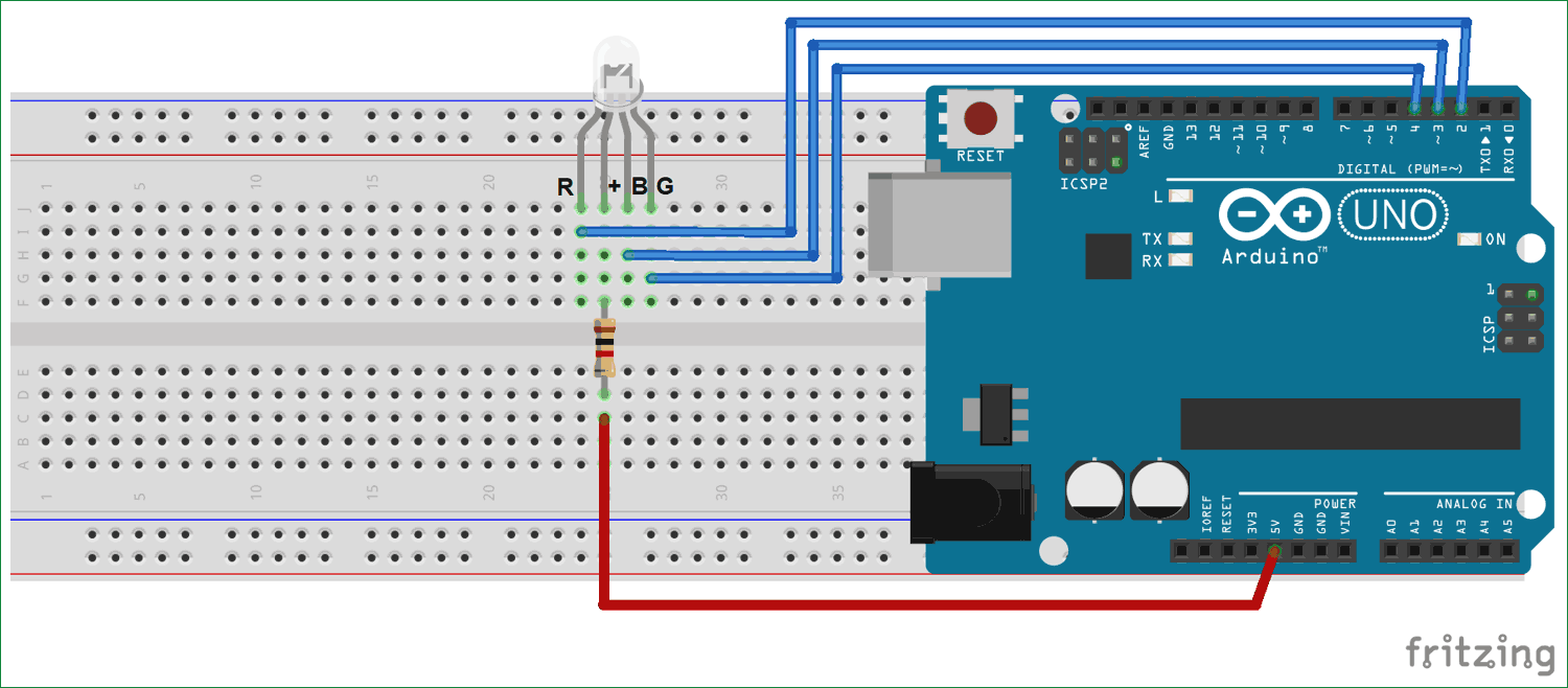
RGB LED includes four pins: Common (Cathode-) pin: needs to be connected to GND (0V) R (red): pin is used to control red G (green): pin is used to control green B (blue): pin is used to control blue To connect RGB LED to Arduino, we need to use current-limiting resistors. This can make the wiring complex.
Arduino Project 27Arduino RGB LED experiment
Schematics In this example, the WS2812B LED strip will be powered using the 5V Arduino pin. In my case, I'm controlling 14 LEDs. If you want to control many LEDs, you'll need to use an external power source. Useful tips: Connect a capacitor with a capacitance between 100uF and 1000uF from power to ground to smooth out the power supply.

Arduino Uno RGB LED Demo YouTube
Step 1 - Connecting the RGB LED RGB LED Basics Common Cathode and Common Anode RGB LEDs Controlling the LED Brightness with PWM Step 2 - Connecting the Three Potentiometers Using a Potentiometer as an Analog Input Step 3: Arduino RGB LCD Example Code How the Code Works Additive Color Conclusion Supplies
RGB Led with Arduino UNO Example Techatronic
Code 1. PWM or pulse width modulation is the technique that is used to control the brightness of the LED, speed, and direction of different types of motors. Arduino Uno has six pins (3, 5, 6, 9, 10, and 11) to generate PWM signals of the specific duty cycle. The duty cycle specifies the duration for which the pulse is HIGH.

Arduino uno with 16x32 RGB LED matrix panel clock prototype YouTube
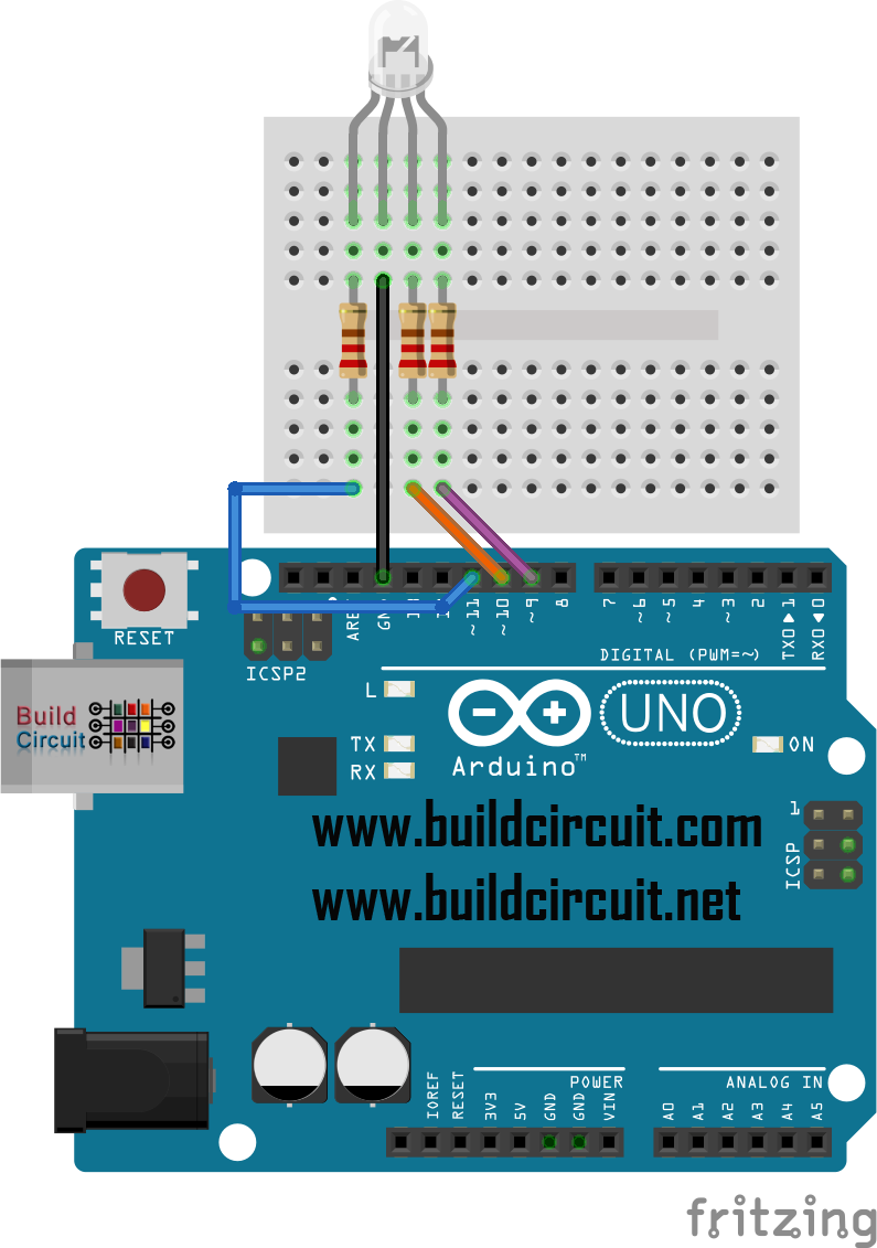
Step 1: Components 1. Arduino Uno/other boards can work too but check which pins provide PWM 2. Three 220 ohm resistors (if you don't have 220 ohm resitors you can use resistors that are in range of 55 ohms - 220 ohms) 3. 4 jumper wires 4. at least one RGB 5mm LED 5. one breadboard Ask Question Step 2: Connecting Components
Rgb Led Chaser Using Arduino Uno Details Hackaday.io
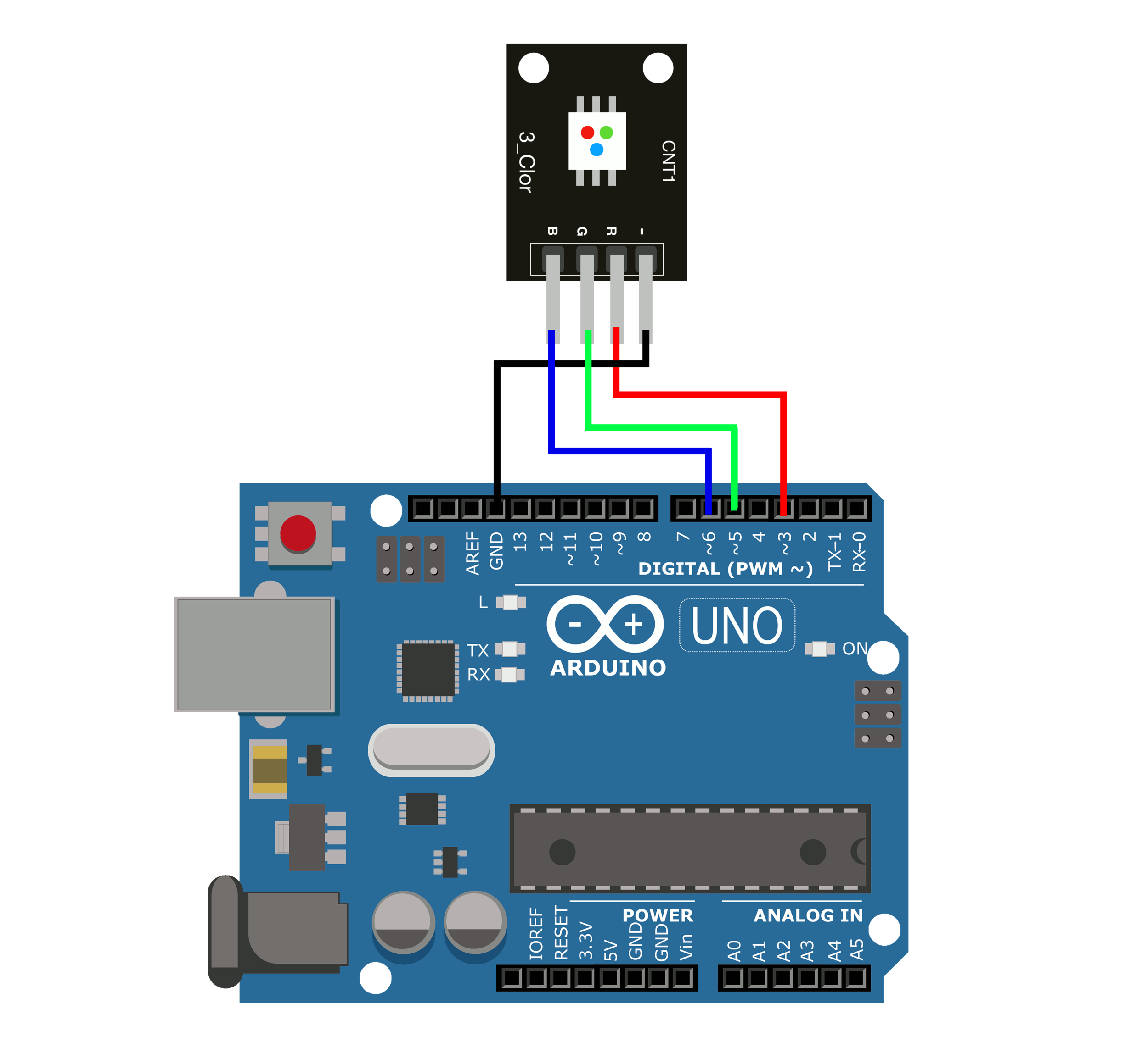
To connect the RGB LED module to the Arduino Uno simply connect the - pin to the Arduino Gnd. Connect the R, G, B pins to the Arduino PWM pins 9, 10, and 11. Connect the Signal pin to the Arduino I/O (Input/Output) pin, because the Arduino will detect the button press with the help of this pin. This allows the Arduino to read the state of the.

Interfacing Arduino Uno with RGB led Arduino Project Hub
An RGB LED has 4 pins, one for each color (Red, Green, Blue) and a common cathode. It has tree different color-emitting diodes that can be combined to create all sorts of color! Any color is possible depending on how bright each diode is. In this tutorial you will learn how to use an RGB LED with Arduino and create unique color combinations.

RGB LED with potentiometer Arduino tutorial Codebender Blog
Arduino Uno Breadboard (and some breadboard wires) 3 x Resistor (220 Ω) RGB LED There are two types of RGB LEDs: Common Anode and Common Cathod e. We'll provide example schematics and code for both types below. How To Connect an RGB LED to an Arduino Here's the schematic for the circuit.

How to Control an RGB LED Strip Arduino Tutorial Arduino, Arduino led, Rgb led
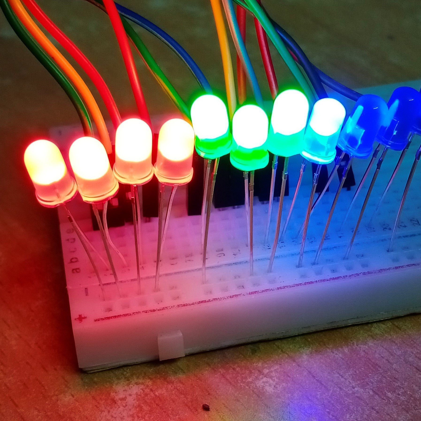
An RGB LED, short for Red-Green-Blue Light Emitting Diode, is a unique electronic component consisting of four pins: one for each primary color—Red, Green, and Blue—along with a common cathode or anode, depending on the type of RGB LED you're using.The magic of an RGB LED lies in its ability to emit a wide range of colors by adjusting the brightness of each color diode.
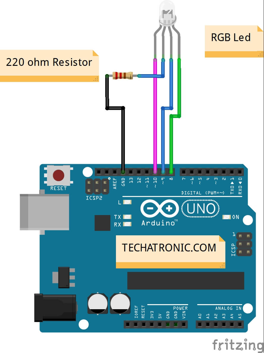
RGB Led with Arduino UNO Example TECHATRONIC
Arduino UNO RGB Led (Common Anode) Jumper Wires Breadboard 220-ohm Resistor USB cable to connect Arduino UNO with computer RGB LED with Arduino Circuit Diagram Red pin of Led to D8 of Arduino UNO Green pin of Led to D9 of Arduino UNO Blue pin of Led to D10 of Arduino UNO GND pin of Led to GND of Arduino UNO with 220-ohm Resistor in between

RGB LED With Arduino Uno R3 7 Steps Instructables
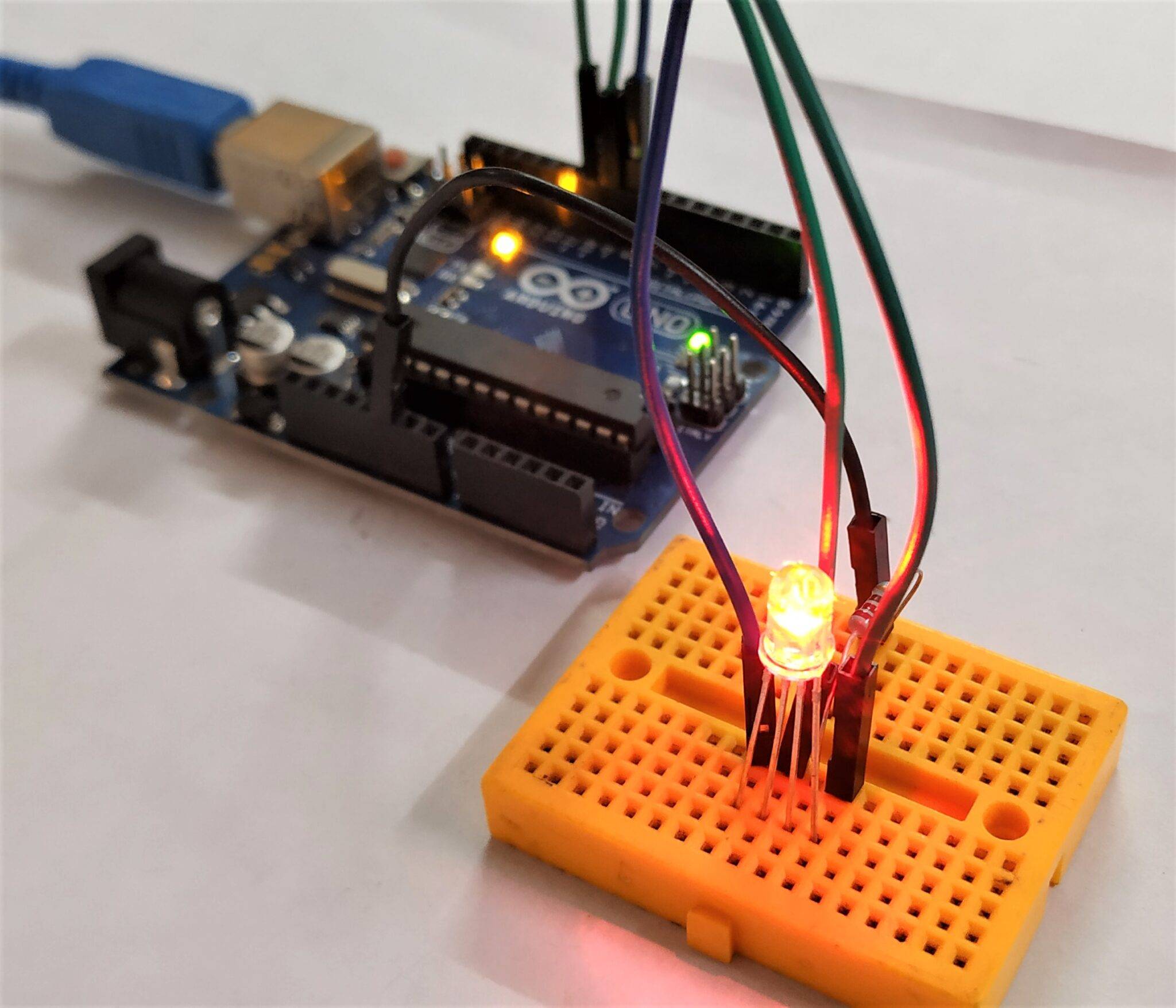
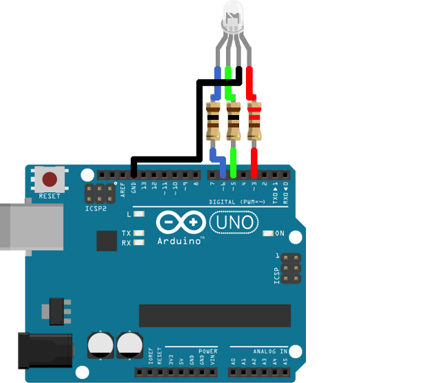
Connecting an RGB LED with an Arduino is very simple. Here I will show you how to connect a common cathode RGB LED to an Arduino Uno Board. From the above image, you can see that I connect the common cathode pin to the ground pin and connect the other three pins to the Arduino PWM output pin - 3, 5, and 6 using three 220 Ohm (Ω) resistors..

Multiple RGB Led Chaser Using Arduino Uno Arduino Project Hub
Step 1: Components - Arduino Uno board * 1 - USB cable * 1 - Resistor (220Ω) * 1 - RGB LED * 3 - Breadboard * 1 - Jumper wires Step 2: Principle RGB LED means red, blue and green LEDs. RGB LED can emit different colors by mixing the 3 basic colors red, green and blue.
Arduino Breathing LED Functions — Maker Portal
To code an RGB LED in Arduino, you need 3 PWM output pins. 1- Set The PWM pins as output pins using the pinMode() function. 2- Connect the PWM output pins to the R, G, and B terminals on the LED. 3- Connect the RGB ground lead to the Arduino's ground. 4- Pick a desired color and get its (R, G, B) color code.
How to setup a rgb led on arduino uno
Search 9 Cingoli custom curtains, drapes & blinds to find the best custom curtain, drape and blind service for your project. See the top reviewed local custom curtains, drapes and blinds in Cingoli, The Marches, Italy on Houzz.

Multiple RGB Led Chaser Using Arduino Uno Arduino Project Hub
Before we get into the Arduino RGB LED configuration, wiring, etc. Let's first go over the basics of the RGB LED itself. The RGB LED consists of 3 LEDs in one. A red, a green, and a blue LED all in the same housing with separate leads for each. This allows the LED to mix colors at different intensities, allowing the presentation of many.